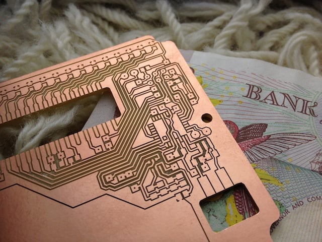
The most useful thing a computer controlled mill could do for me is make circuit boards. It’s a nice thing to get started with, anyway. Here’s the first one I milled:
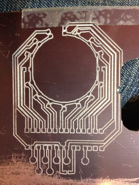
Oh dear. Doesn’t look very good. The mill was gouging too deeply into the board, but that’s up to me to correct in the software. The more serious problems are backlash related. The circular pattern on the board has flat edges on the left and right where there’s too much slop in the leadscrew mechanism. Tell the mill to move right 10mm, then left 10mm and the head should be exactly back where it started. If the nuts and leadscrews are too loose then some of the motion gets lost in the mechanism, leaving you with flat-sided circles, or cuts in the wrong places – you can see that the square pads near the bottom ought to be evenly spaced, but they’re not.
I tightened up the mechanism a little bit and had another go:
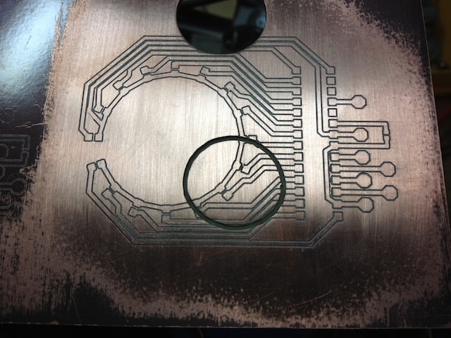
Much better. Not perfect, but getting there. (Ignore the circular cutouts – they were there beforehand.) A few more tweaks and I finally managed to get rid of most of the backlash.
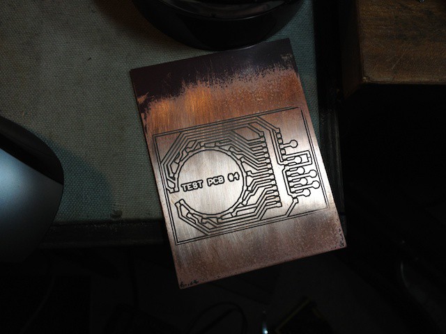
There’s still a tiny bit of slop, but the error is small enough for me to start making more complex boards:
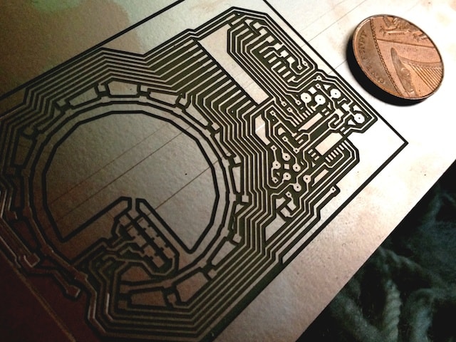
The nice thing about carving PCB designs with a mill rather than using the traditional acid-etching process, is that I can get the mill to cut the board out as well as just carving the pattern on the PCB:
