A friend found a stack of discarded LED assemblies in a skip, and threw them my way. Amongst the other bits, there were several Dialight Lumiled strips – nicely machined aluminium backplates with 6 bright white 1-Watt LEDs mounted on top. They’re designed to be run from a proprietary power supply that delivers around 19.2 volts at a tightly controlled 350mA. So, not the sort of thing you can wire up to a car battery.
I figures this was as good a time as any to start embarking on analogue electronics – gotta dip your toe in the water at some stage. So, after several hours of wading through various “solutions” on Farnell’s website, I came across a tiny little chip that claims to be designed specifically for driving blocks of 6 LEDs like this. The datasheet showed an example circuit along with the specifications of the extra components needed, so I ordered the bits and designed a little board.
It’s a boost driver, which means it can produce a higher voltage output than the voltage you put in. Power in and out are roughly the same, though; so it takes more current input than the current it can provide at the output.
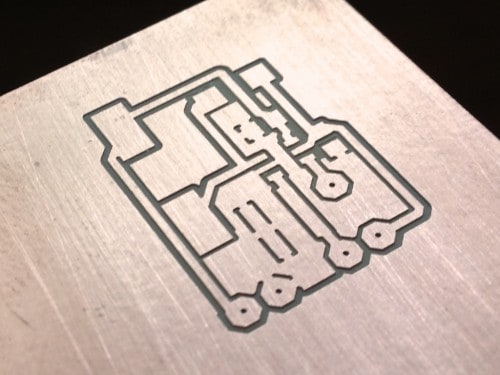
I designed the PCB in Eagle, and used a free plugin/script to convert the pattern into G-code for my mill to understand. Gotta write more about my mill another time – for me, this is where it shines. It took about 5 minutes to carve out this little circuit, much much faster than etching a board in acid, the old way.
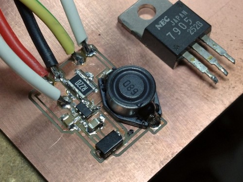
Soldering the components on was a little bit fiddly but doable. I find it helps, when soldering multi-legged components like the little SOT3-6 driver chip, to wet all the pads on the board with solder first, using solder wick to remove all but the thinnest little layer.
The board worked first time. Which shouldn’t have been surprising, given that it was the manufacturer’s design, but I never seem to imagine things will go that easily… And the little driver circuit is small enough to mount inside the lights’ cases, too, so I’m going to have to make up a batch of them.


ok all led are parallel?