My speedo cable snapped. Boo. The speedo was never very accurate anyway, so rather than replace the cable I figured it’d be fun to try making a digital speedo – plus it’s an opportunity to try using surface mount components rather than the bigger through-hole ones I’ve used so far.
A bit of an ambitious design this time round – separate display and control boards, bigger and more complicated than anything I’ve done to date:
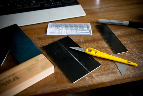
First – hacking up bit of unetched PCB. You get through a lot of stanley knives like this.
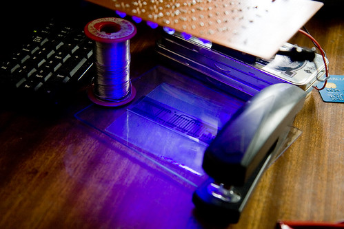
Exposing the board:
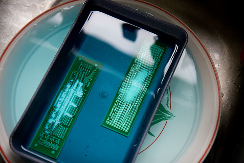
Etching it:
The tracks on it are tiny this time around:
Ended up having to redesign part of the board as the pads were too small for me to drill holes through. I need a better drill. Still, good practice for tring to solder some of the tiny SMD components on:
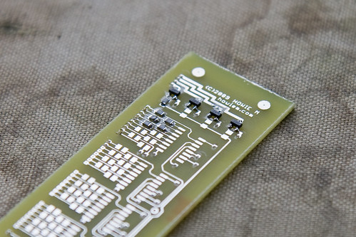
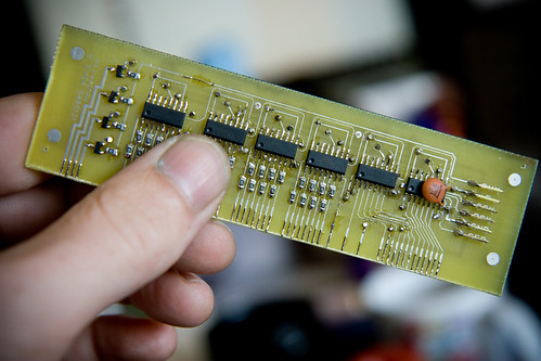
New design, etched and with all the components on. SMD components are actually much quicker and easier to solder than through-hole, it turns out. The board’s a bit messy ‘cos some of the tracks broke and I had to solder little strands of wire across to fix them, but still:
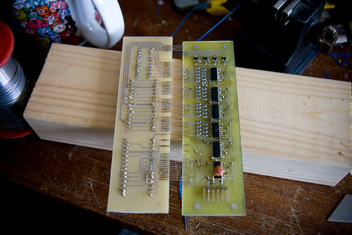
With the control board finished, it was time to connect it to the display board (which will house the actual LED displays). To connect it up meant over 50 tiny little wires had to be stripped and soldered to each board:
Finally, all the wires are soldered up – the boards are connected …
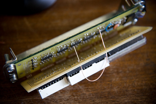
… this is what it looks like from the back:
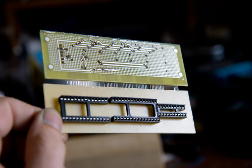
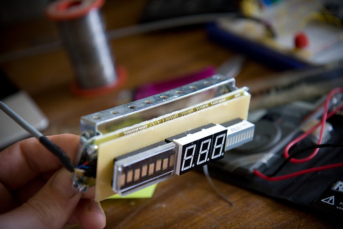
The displays plug into the sockets on the display board:
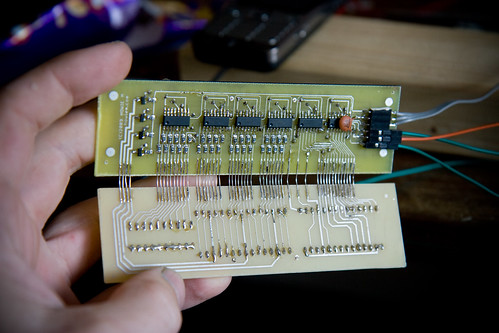
The boards fold together, using all those little wires as a hinge. I made a simple Meccano frame to hold the boards (rather than create a neat box to put the whole thing in, I quite like having it all guts-out)
A little wire loop holds the bottom of the boards together so they don’t flap around:
Done:
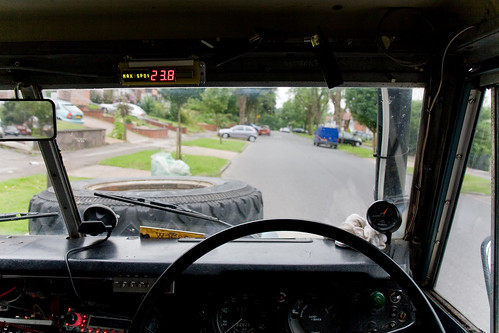
Then a couple of magnets holds the thing to the windscreen frame on my truck. Magnets rule.
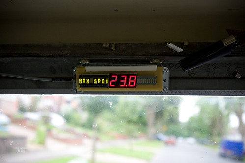
And this is the final thing – in position, working. Normally it shows the speed, but when it detects the Landrover hasn’t moved for 5 seconds it alternates between showing the trip distance and my maximum speed on the trip:
And the best thing is that it’s a darn sight more accurate than almost all dial-based speedos, especially factory fitted ones (most car speedos read 4-5mph faster than you’re actually going, to err on the side of caution – when your car speedo says you’re doing 30mph, you’re probably only going 25-26mph. The manufacturers figure it’s safer to have you going slower than you think rather than the other way around – compare your speedo with your satnav’s speed readout if you have one).
*** UPDATE ***
Had a few questions about this thing by email, so a few more details:
– The thing runs off an Atmega328. That’s what’s so cool about Arduinos – once you’ve got your circuit and code working, you can take the programmed chip out of the Arduino board and solder it into a stripboard with a crystal, 2 capacitors and 2 resistors and it’ll carry on working. Then you can stick a fresh chip in the Arduino (at a cost of about £1.50) and get on with the next project.
– The sensor is an Allegro Hall Effect sensor, which gets triggered by a tiny magnet stuck to the propshaft. The time between the pulses is inversely proportional to the speed you’re going, so it’s a quick simple calculation for the Arduino.
– The left-most display is an HDSP-2113 smart alphanumeric display. Takes a good few data lines to drive all the displays, hence the use of all the shift registers (74HC595s) on the rear PCB. Shift registers ru-u-u-ule.

