So.
In the bad old days, I chucked some solar panels on our extension roof, ran some cables to the attic, and had this sort of mess going on:
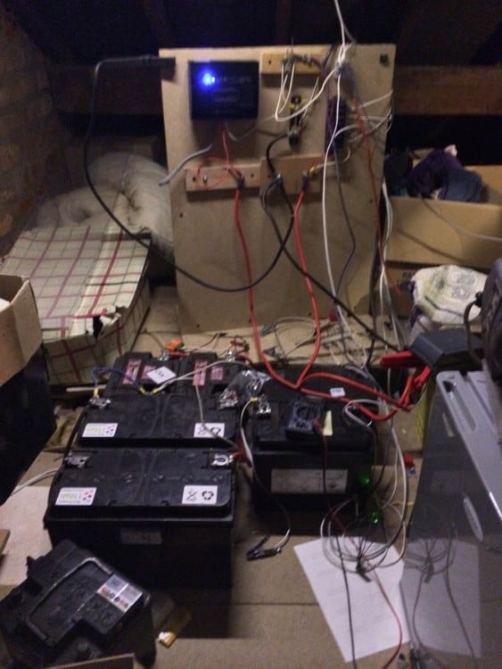 Cheapo MPPT solar battery charger connected to lots of old car batteries.
Not pretty, but it let me wire the house for 12v, and fit lots of lighting and stuff that wasn’t reliant on the grid. Finally got round to tidying it up last year…
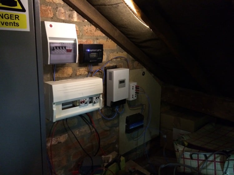 Consumer units work fine with low voltage stuff if all you need is switching – but don’t rely on the breakers to do anything useful. Made everything a lot tidier though.
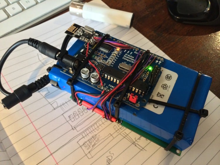
Wanted a way to monitor everything without having to go up into the attic, though. So I stuck an Arduino with an NRF24L01 transceiver in the main box:
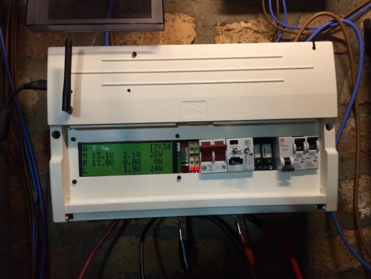 … and started making some little receivers.
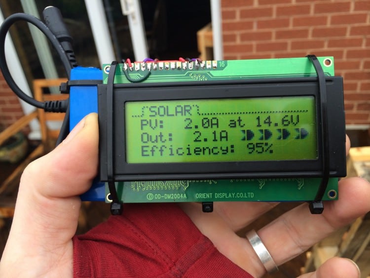
First one was an Arduino and an LCD, cable-tied round a rechargeable battery:
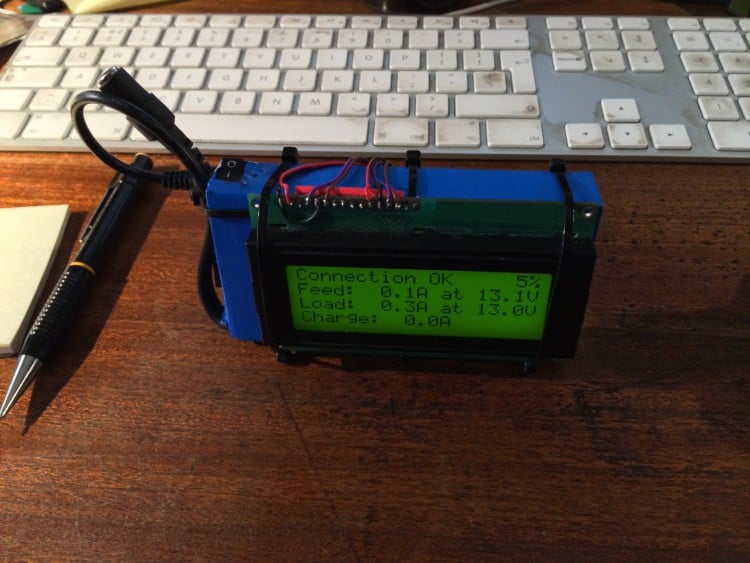
Found some cheap but big LCDs on eBay, so I did the ole’ “solder an Arduino straight to it” trick:
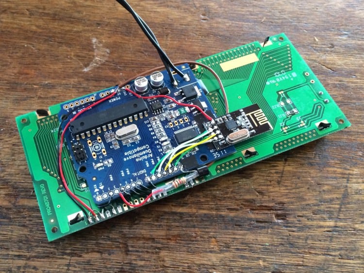 Definitely neater – can run off a 9V battery or straight from the house’s 12V supply:
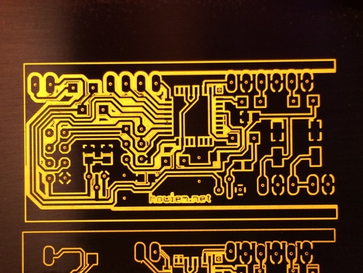
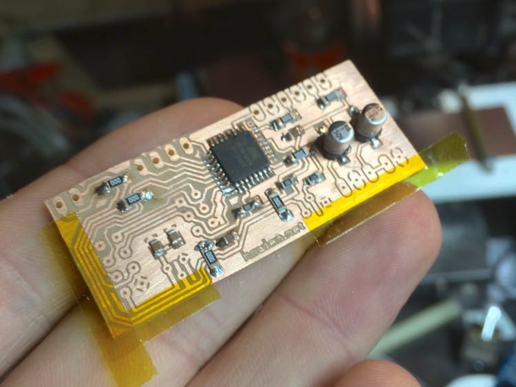
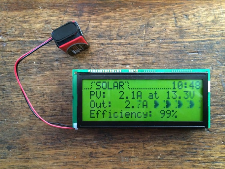 … but by now I was wanting more of these round the house. Time to cut a little PCB on the mill:
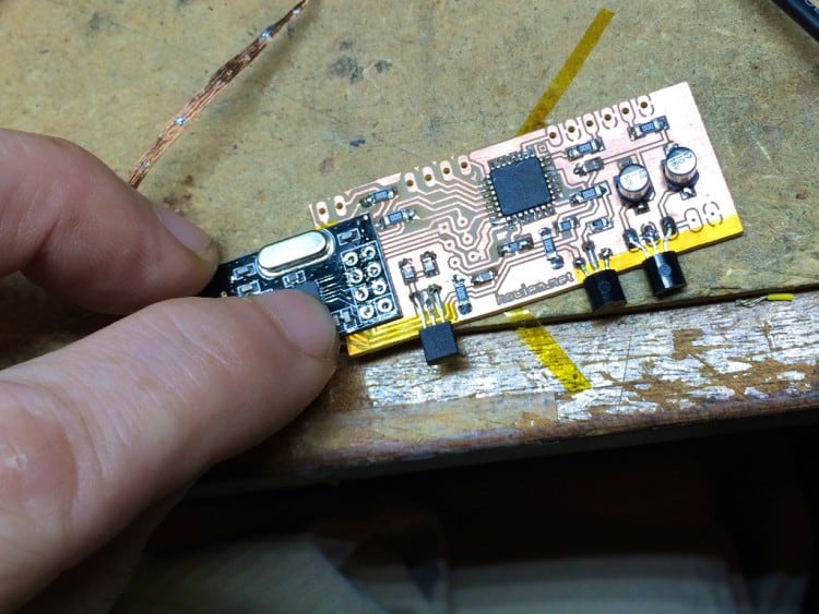
The transceiver module connects to the Atmega with 8 pins – but I didn’t want to drill holes to connect it, though: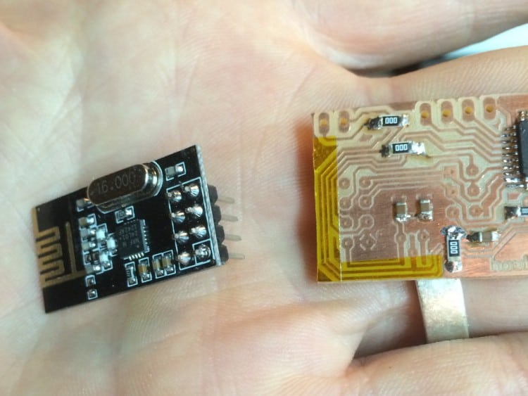
So I came up with a cheeky pin-less solution. First, remove all the header pins from the module:
… making sure the holes were completely clear of solder. Had to make sure the underside of the board was clear of any little solder splashes.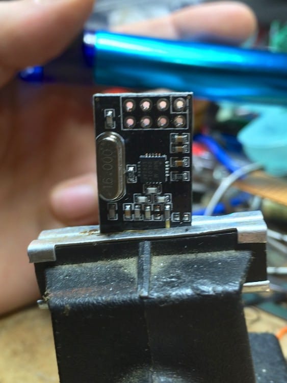
Then I put a nice round blob of solder on just two of the matching pads on the PCB, diagonally opposite each other – this let me jiggle the module around a little and feel when the holes were aligned with the pads. Before putting the module in place, I slathered plenty of flux on the other pads to help with the next bit.
Touched those two pads with the soldering iron to “tack” the module down, then I filled the rest of the holes with solder.
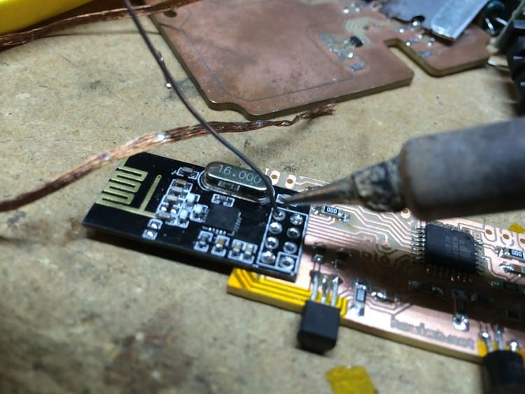
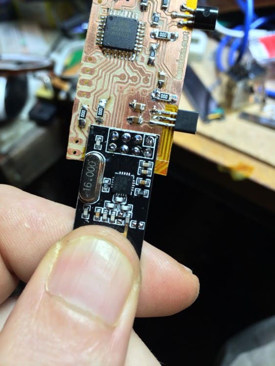
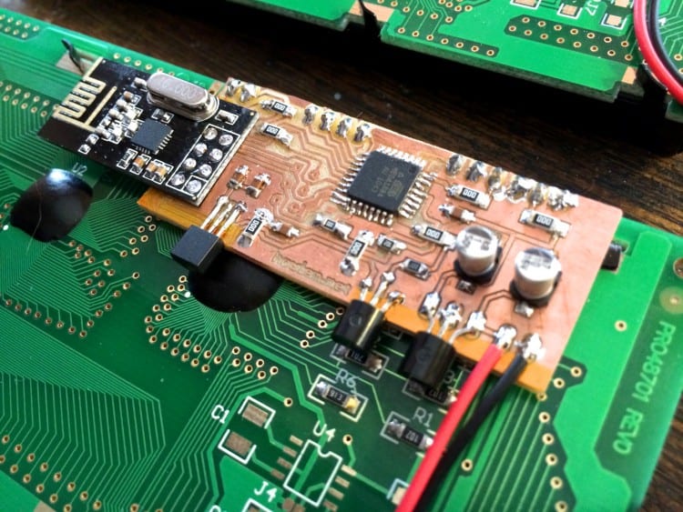 Voila. No short-circuits (wish I could say every time I’ve done this trick since, it’s worked as well, but it sometimes goes wrong)
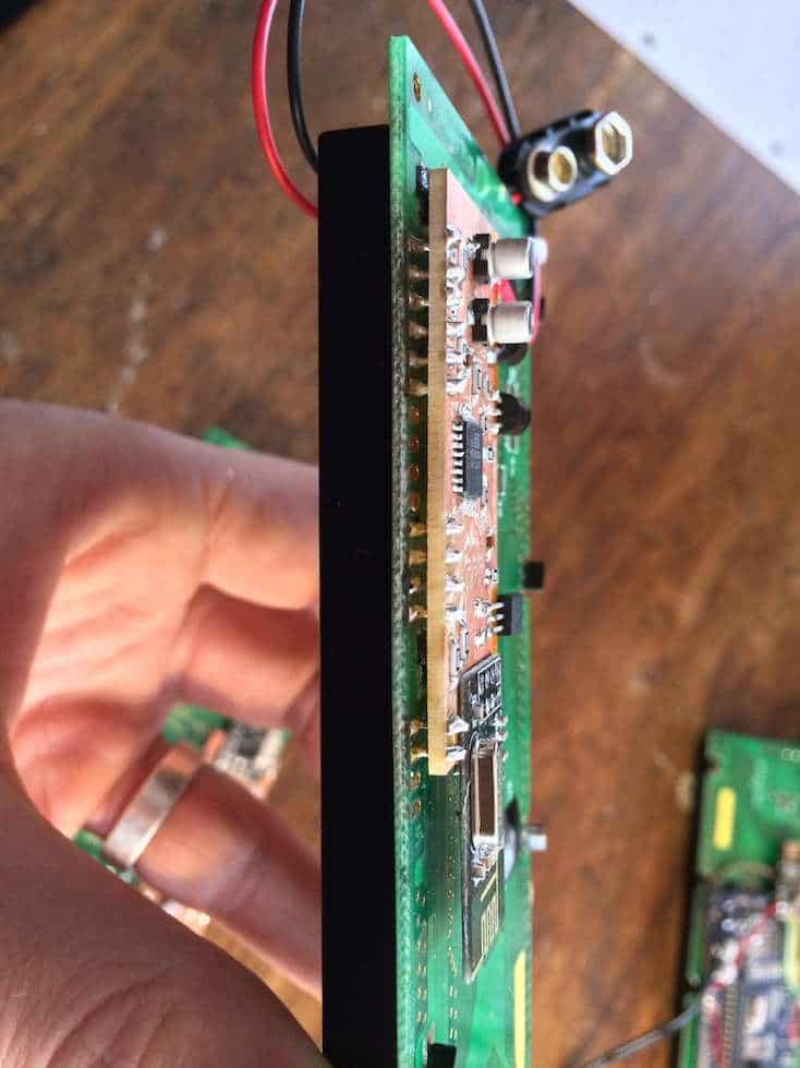
Makes for a super-skinny display. In hind-sight, I’d have probably tried to find a better way to mount the electrolytic caps – they really do stick out a bit. Maybe upside down, poked through a hole in the PCB, but soldered on top?
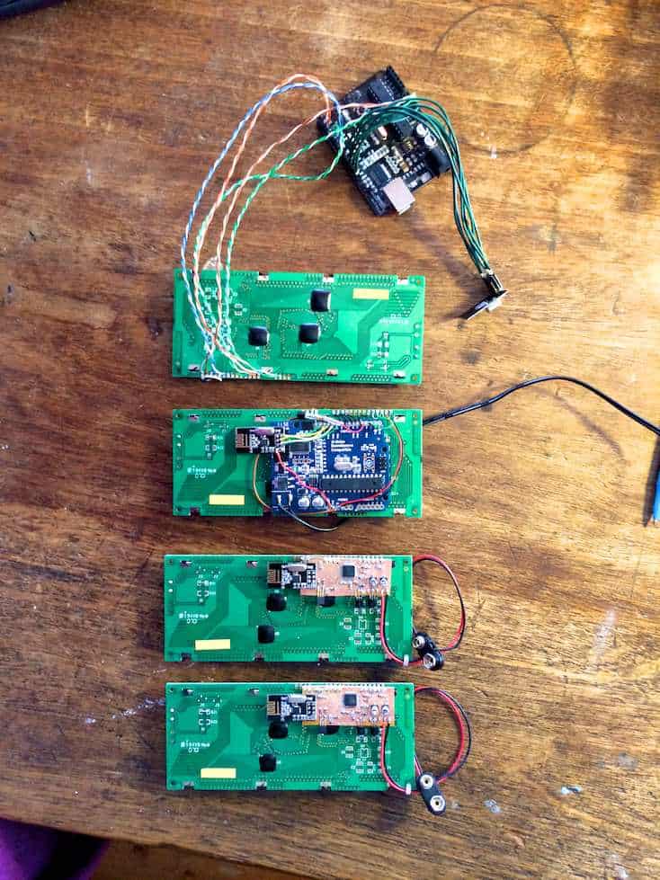
The collection, then – prototype at the top, hacky sacrifice-an-arduino version, and a couple of tidy ones:
